 Moto Guzzi V85 TT - Service manual > Modulator
REMOVAL
- Remove the engine from the vehicle
PREPARING THE VEHICLE
- Connect the bleeder bottles to the front and rear calliper bleeder screws and open them.
- Press the front brake lever and the rear brake pedal as far as they will go and block them in position using the clamping devices. Close the front and rear calliper bleeder screws and remove the bleeder bottle
- Mark a reference on the pipes and on the ABS control unit to avoid inverting them when refitting
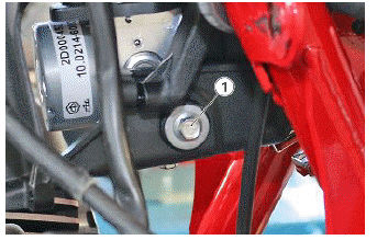
- Undo and remove the screw (1)
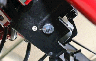
- Undo and remove the screw (2)
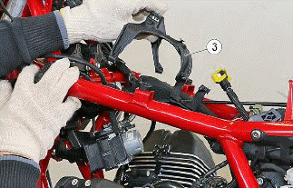
- Remove the support bracket (3)
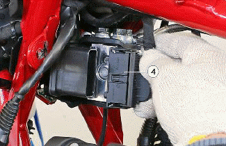
- Disconnect the connector (4)
- Unscrew and remove the screws (5)
- Remove the ABS control unit (6)
NOTE FIRST OF ALL, DISCONNECT THE LINES BETWEEN THE ABS CONTROL UNIT AND THE BRAKE MASTER CYLINDERS AND SEAL THE OPEN COUPLINGS ON THE ABS CONTROL UNIT IMMEDIATELY USING PROTECTIVE PLUGS. NEXT, REMOVE THE LINES BETWEEN THE ABS CONTROL UNIT AND THE BRAKE CALLIPERS AND SEAL THESE COUPLINGS USING PROTECTIVE PLUGS TOO.
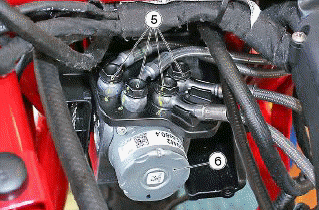
INSTALLATION
- Remove the ABS modulator
- Install the new completely pre-filled ABS control unit
- In order to ensure that the brake fluid remains inside the ABS control unit, first remove the protective plugs from the braking circuit couplings and connect the corresponding lines.
- Once all the braking circuit lines have been connected, remove the protective plugs from the couplings of the brake master cylinders and connect the respective lines to the ABS control unit.
- Remove the clamp from the front brake lever and the rear brake pedal
- Remove the caps from the reservoirs and fill them with new brake fluid
CAUTION PERFORM THE STANDARD BRAKING SYSTEM BLEEDING PROCEDURE, AS DESCRIBED AT THE END OF THE CHAPTER.
- Fill the reservoirs and refit the caps
- Check the stroke and sensitivity of the front brake lever and the rear brake pedal
- If the brake pedal or lever stroke is too long after carrying out the bleeding procedure, check the braking system for leaks and, if none are found, bleed the system using the diagnostic tool, as described.
- Disconnect the flexible bleeder pipes and re-tighten the bleeder screws, applying the correct torque
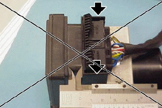
ABS CONTROL UNIT CONNECTOR INSERTION PROCEDURE
- Check the initial position of the connection clip lever.
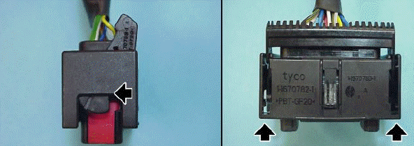
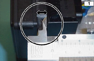
- When the connector is fully inserted, the distance between the connector and the ABS control unit must be 7.5 mm (0.29 in).
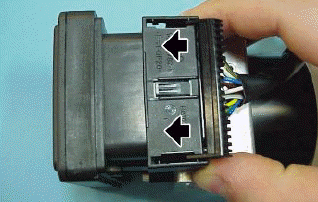
- If the initial position of the connector and the driving lever is not that shown in fig. 1, the connector will not be properly coupled and the distance measured will be greater (12 mm approx. (0.47 in) ). In this case repeat the operation as described in the two previous points.
IT IS ADVISABLE TO CREATE A TEMPLATE TO CHECK THE CORRECT CONNECTOR INSERTION.
See also:
 Moto Guzzi V85 TT - Service manual > Operating diagram
ABS functional diagram key Front system circuit Front brake master cylinder Front brake control lever Rear system circuit Rear brake pump Rear brake pedal control ABS control unit Rear brake calliper Front calliper (2 callipers) Front brake circuit intake solenoid valve (normally open) Humidifier Rear brake circuit intake solenoid valve (normally open) Rear brake exhaust circuit solenoid valve (normally closed) Rear/front brake circuit low pressure accumulator Front brake exhaust circuit solenoid valve (normally closed) DC electric motor Double circuit hydraulic pump (ABS) Rear brake reservoir Front brake reservoir
 Moto Guzzi V85 TT - Service manual > Component maintenance
The vehicle is equipped with two-channel ABS. In other words, it works on both the front and rear wheel. Periodically and each time the wheels are remounted, the phonic wheel or the sensor is replaced, it is important to check that the distance is consistent over all 360Âş. To do this, use a feeler gauge and check the distance between the sensor and the phonic wheel on three points at a distance of 120Âş.
 Ducati Scrambler
 Fantic Caballero 500
 Indian FTR 1200
 Moto Guzzi V85 TT
 Royal Enfield Bullet Trials Works Replica
 Triumph Scrambler 1200 XE
 Triumph Street Scrambler
 Yamaha XSR700
 Ducati Scrambler 800
 Moto Guzzi V85 TT
 Triumph Scrambler 1200 XC