 Moto Guzzi V85 TT - Service manual > Electrical system installation
TABLE C - PRELIMINARY PHASE
- Proceed as indicated in the figure
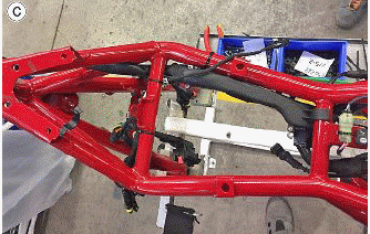
TABLE D - PRELIMINARY PHASE
1. Plastic rivet (female) + plastic rivet (male)
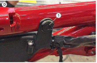
TABLE E - PRELIMINARY PHASE
- Proceed as indicated in the figure
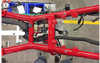
TABLE F - PRELIMINARY PHASE
1. Medium sized clamp
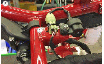
TABLE G - PRELIMINARY PHASE
1. Medium sized clamp
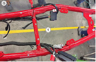
TABLE H - PRELIMINARY PHASE
- Arrange the wiring as illustrated in the figure
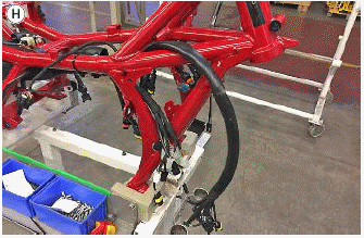
TABLE I - PRELIMINARY PHASE
- Arrange the wiring as illustrated in the figure

TABLE J - PRELIMINARY PHASE
- Arrange the wiring as illustrated in the figure
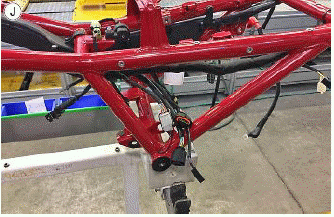
TABLE K - ABS SYSTEM PRE-MOUNTING
- Large clamp (for canister filter)
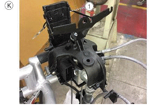
TABLE L - ABS SYSTEM PRE-MOUNTING
- Large clamp (for canister filter)
- Medium sized clamp
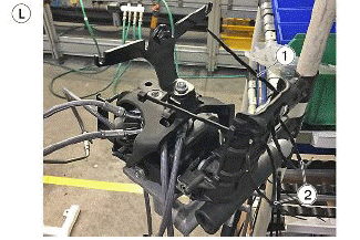
TABLE M - ABS SYSTEM PRE-MOUNTING
- Large clamp (for canister filter)
- Medium clamps (pre-mounted for subsequent flywheel cables fastening)

TABLE N - ASSEMBLY OF FRAME UNIT TO ENGINE
- Temperature bulb connector
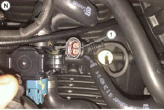
TABLE O - ASSEMBLY OF FRAME UNIT TO ENGINE
- Temperature bulb connector

TABLE P - ASSEMBLY OF FRAME UNIT TO ENGINE
- Temperature bulbs connections carried out and objectified

TABLE Q - ASSEMBLY OF FRAME UNIT TO ENGINE
- Gear in neutral switch
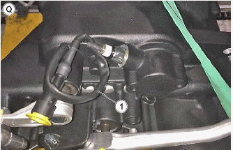
TABLE R - ASSEMBLY OF FRAME UNIT TO ENGINE
- Pick up sensor rubber piece
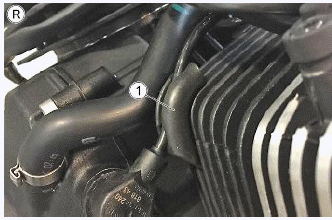
TABLE S - ASSEMBLY OF FRAME UNIT TO ENGINE
- Medium sized clamp
- Large clamp
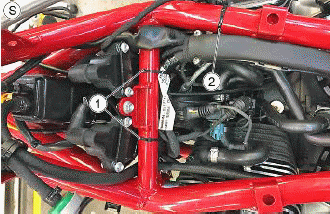
TABLE T - ASSEMBLY OF FRAME UNIT TO ENGINE
- Fall sensor
- Fuel pump
Pass the fall sensor and fuel pump outputs under the frame bracket as illustrated in the figure
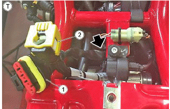
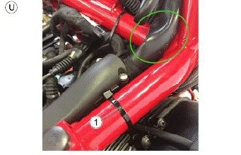
TABLE U - ASSEMBLY OF FRAME UNIT TO ENGINE
- Large clamp
Pass the branch that goes to the instrument cluster over the frame crosspiece as illustrated in the figure
See also:
 Moto Guzzi V85 TT - Service manual > Front side
TABLE A - VOLTAGE REGULATOR ASSEMBLY Regulator side flywheel cable Regulator cable to wiring harness
 Ducati Scrambler
 Fantic Caballero 500
 Indian FTR 1200
 Moto Guzzi V85 TT
 Royal Enfield Bullet Trials Works Replica
 Triumph Scrambler 1200 XE
 Triumph Street Scrambler
 Yamaha XSR700
 Ducati Scrambler 800
 Moto Guzzi V85 TT
 Triumph Scrambler 1200 XC