 Ducati Scrambler 800 - Service manual > Airbox - throttle body
Refitting the throttle body
Position the throttle body inside the airbox.
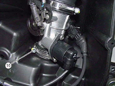
Fix it by tightening clip (16) to a torque of 1.5 Nm +- 10%.

Refit the remaining part of the airbox as described in paragraph "Refitting the airbox".
Refitting the intake manifold and injectors
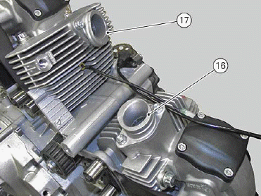
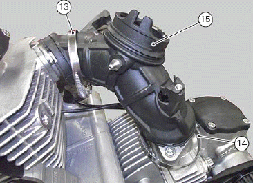
Position the intake manifold (15) with relevant clamps (13) and (14) on the horizontal cylinder manifold (16) and the vertical cylinder manifold (17).
Tighten the two clamps to a torque of 3 Nm +- 10%.
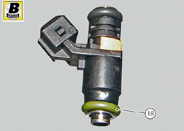
Apply specified grease to the O-ring (18).
Insert injector (11) of the horizontal cylinder in injector (12) of the vertical cylinder, in the suitable seat (A) on the intake manifold (15).
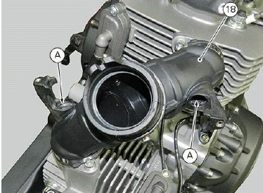
Important In order to avoid damaging the O-rings of the injectors, fit the injectors into the unions fully home, keeping them in line with their relevant seat.
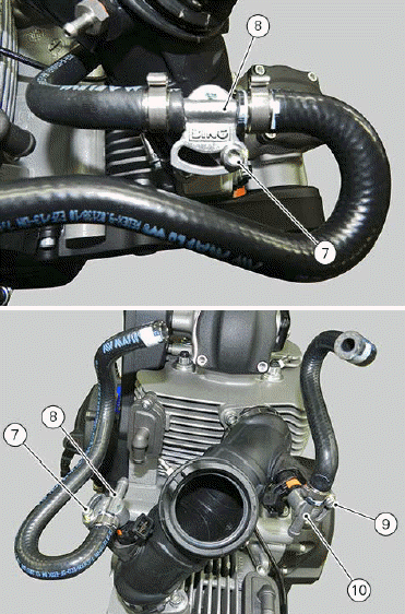
Fit union (10) on the vertical cylinder injector as shown in the figure.
Tighten the screw (9).

Fit union (8) on the horizontal cylinder injector as shown in the figure.
Tighten the screw (7).
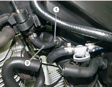
Connect the Map Sensor hose (3) and fix it with clip (4).
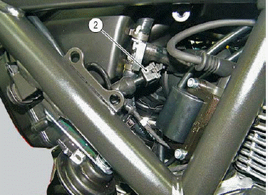
Reconnect the horizontal cylinder connector (1) and the vertical cylinder connector (2).

Removing the throttle body
Remove all components up to the throttle body as explained in paragraph "Removing the airbox".
After releasing the throttle body from the wiring and the throttle cable, loosen clip (16) to remove it.
Removing the intake manifold and injectors
After removing the airbox, proceed as follows.
Disconnect the horizontal injector (1) and the vertical injector (2).

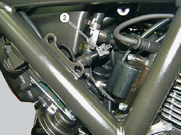
Disconnect the Map Sensor hose (3), removing clamp (4).

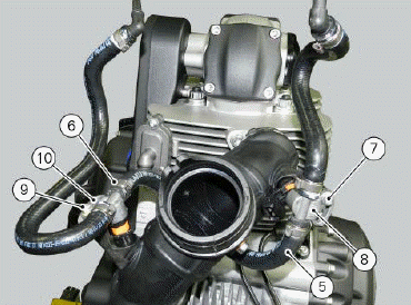
Disconnect hose (5), removing clamp (6).
Undo the screw (7) and remove the horizontal cylinder head injector union (8).
Undo the screw (9) and remove the vertical cylinder head injector union (10).
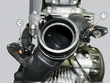
Remove the horizontal cylinder injector (11) and the vertical cylinder injector (12).
Unscrew the two clips (13) and (14) and remove the intake manifold (15).

Refitting the airbox
If previously disassembled, reassemble the airbox as explained below: Fit two vibration damping pads (19) in the relevant brackets and fit spacers (20) as shown in the figure.
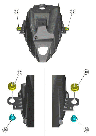
Fit the two clips (21).
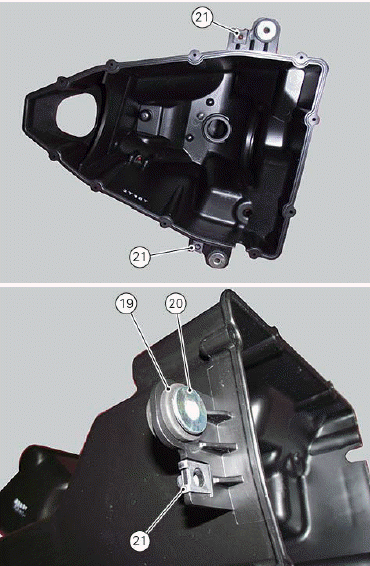

Fit seal (22) in its seat on the airbox.

Fit two spacers (23) as shown in the figure.
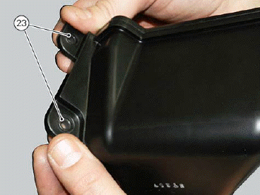
Fit blow-by box (24) fully home on airbox by inserting union in the relevant seat.

Start screws (25) and tighten them to a torque of 3 Nm +- 10%.

Use the indicated product to lubricate tabs (26) of the blow-by box.

Engage the MAP_SENSOR support fully home on the just-lubricated tabs. Apply the specified lubricant in the hole and on pin (28).

Lubricate MAP-SENSOR seal (29) using the specified product.
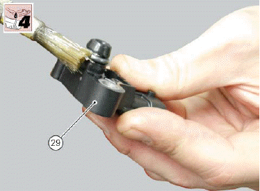
Fit MAP-SENSOR (29) on the support by introducing the pin with O-ring in the support recess and, at the same time, pin in the MAP-SENSOR hole.

To ensure a correct assembly, pin must be pulled, letting the poppet (30) get completely out on the side opposite to insertion.

Fit the pipe (31) with clip (32) in the relevant union of the blow-by box.

Aim hose (31) and the clip as shown in the figure.
Tighten the clip to a torque of 1.5 Nm +- 10%.

Fit seal (33) onto air temperature sensor (34).
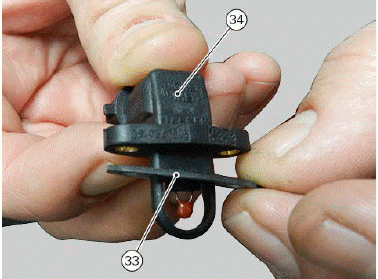
Fasten sensor (34) to the airbox and tighten the two screws (35) to a torque of 1 Nm +- 10%.

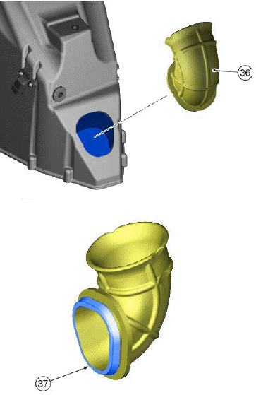
Fit hose (36) fully home on the Airbox by inserting edge (37) fully inside the recess.
Insert the throttle body in the airbox and tighten clip (16) to a torque of 1.5 Nm +- 10%.
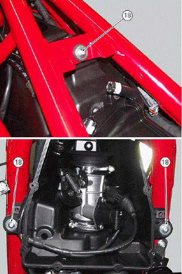
Position the airbox in the frame and fix it by tightening screws (17) to a torque of 10 Nm +- 10%.
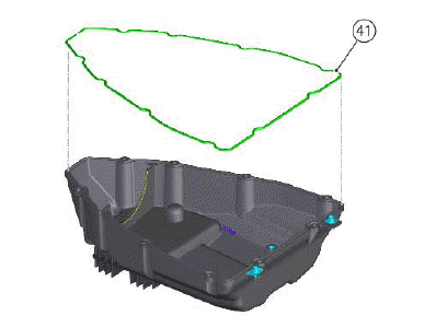
Ensure that gasket (41) is present on the airbox.
If removed, fit the voltage regulator (40) and tighten screws (29) to a torque of 10 Nm +- 10%.

Connect the MAP-SENSOR connector (17).

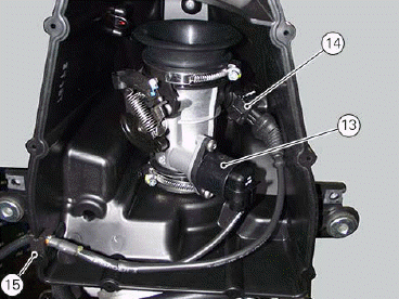
Connect STEPPER motor (13) and potentiometer (14).
Route the cables through the hose guide (15).
Secure the throttle body with clamp (16).

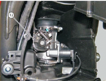
Connect throttle cable (12).
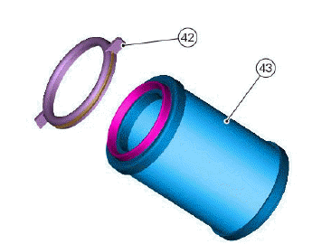
Check that air sensor (43) fits the support (42).
Install the air filter as described in paragraph "Refitting the air filter".
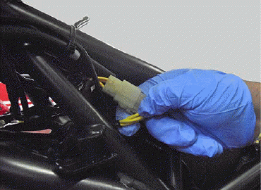
Connect the regulator connectors.
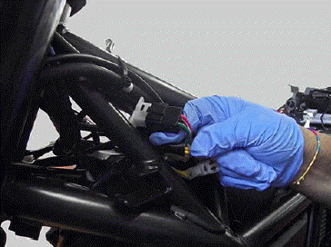
Connect air connector.
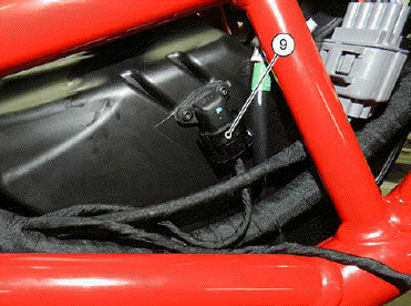
Connect the secondary air system connector (6), connect the secondary air hose (8) and tighten clip (7).
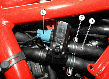
Connect connector (5) of stepper motor and potentiometer.

Position the side body panel so that the two pins (17) of the internal side (15) engage in seats (18).

Secure side body panel (1) by tightening screw (2).
Repeat this procedure on the vehicle opposite side.

Remove the side body panels (Fitting the airbox cover).
Remove the fuel tank (Refitting the fuel tank).
Remove the seat (Refitting the seat).
Airbox cover assembly
RH airbox cover
Position the RH airbox cover (5) so that the upper end is under the tank cover (B).
Start the upper retaining screw (4) of the RH airbox cover (5) and the lower screws (6) with the relevant washers.
Tighten screws (6) to a torque of 8 Nm +-10% and screw (4) to a torque of 5 Nm +-10%.

LH airbox cover
Position the LH airbox cover (7).
Start the upper retaining screw (4) of the LH airbox cover (7) and the lateral screws (8).
Tighten the screws (4) to a torque of 5 Nm +-10 % and the screws (8) to a torque of 5 Nm +- 10%.

Removing the airbox
Remove the seat (Removing the seat).
Remove the fuel tank (Removing the fuel tank).
Remove the side body panels (Removing the airbox cover).
Remove side body panels (1) and (3) loosening screws (2) and (4).
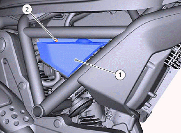
Disconnect connector (5) of stepper motor and potentiometer.

Disconnect the secondary air system connector (6), loosen clip (7) and disconnect the secondary air system hose (8).

Disconnect air connector.
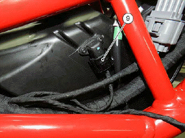
Disconnect the regulator connectors.

Undo screws (11) and remove the airbox cover (10).

Disconnect throttle cable (12).
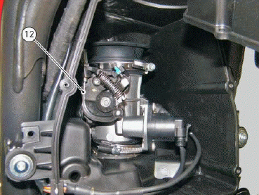
Loosen clip (16).
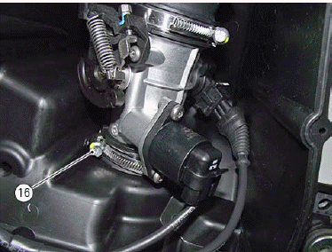
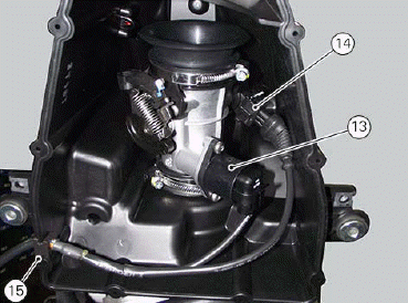
Disconnect STEPPER motor (13) and potentiometer (14).
Release the cables from the airbox by sliding out hose guide (15).
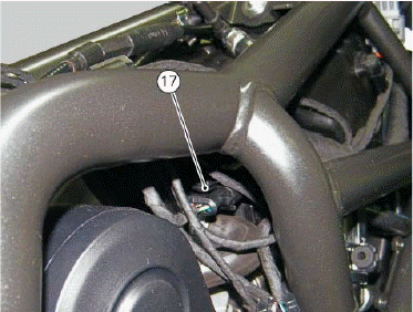
Disconnect the MAP-SENSOR connector (17).
Remove the ties that can obstacle the airbox removal.
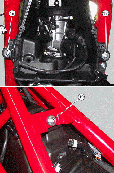
Remove the airbox with the throttle body by loosening the screws (18).
Removing the airbox cover
RH cover
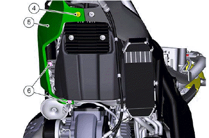
Loosen the upper retaining screw (4) of the RH airbox cover (5) and the lower screws (6).
Remove the RH airbox cover (5).
LH cover
Loosen the upper screw (4) of the LH airbox cover (7), the lateral and lower screws (8).
Remove the LH airbox cover (7).


See also:
 Ducati Scrambler 800 - Service manual > Fuel tank
Refitting the fuel tank Make sure that two silent blocks (16) are present on both sides of the frame.
 Ducati Scrambler
 Fantic Caballero 500
 Indian FTR 1200
 Moto Guzzi V85 TT
 Royal Enfield Bullet Trials Works Replica
 Triumph Scrambler 1200 XE
 Triumph Street Scrambler
 Yamaha XSR700
 Ducati Scrambler 800
 Moto Guzzi V85 TT
 Triumph Scrambler 1200 XC